Wireless tyre temperature sensor
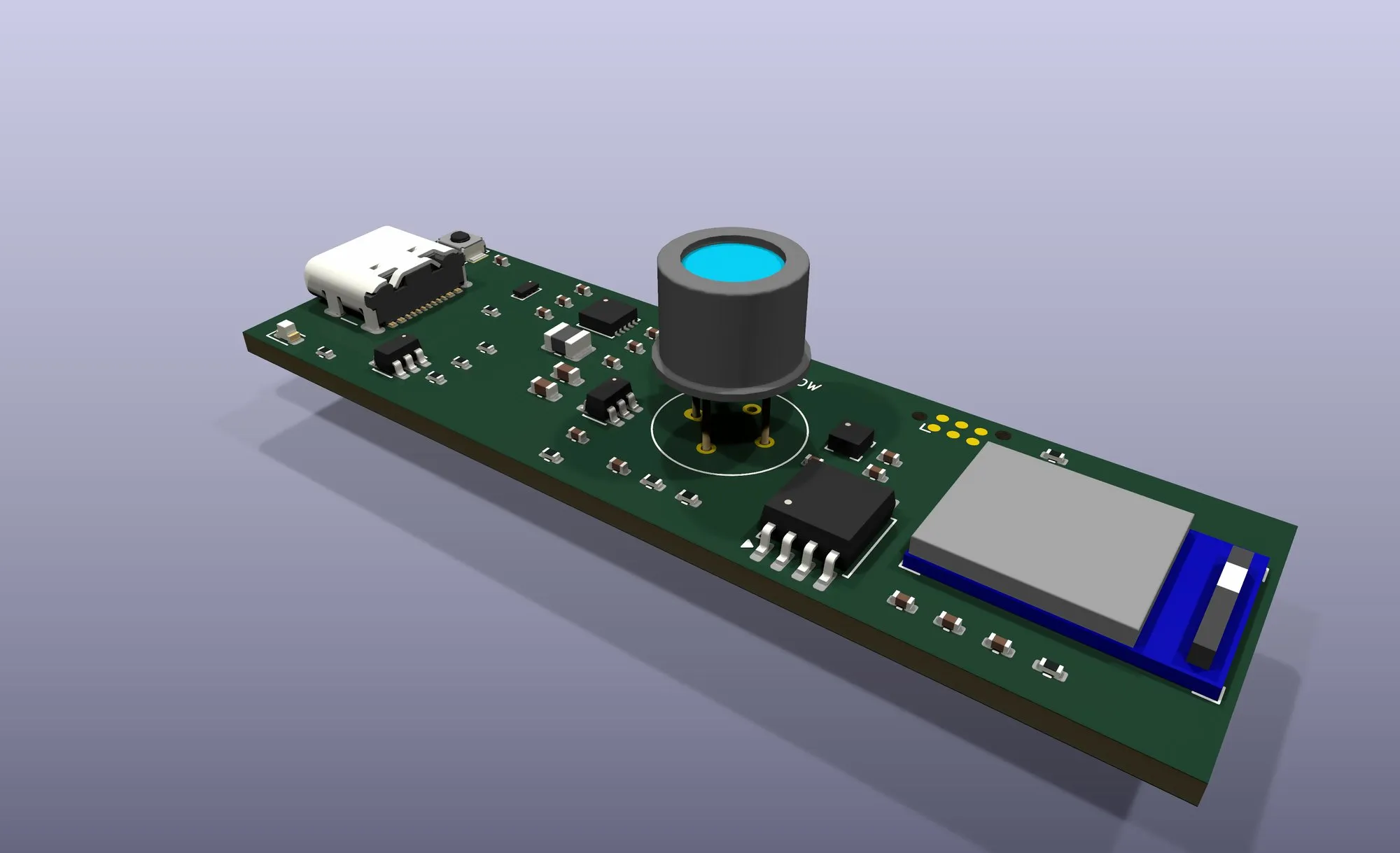
A self-powered sensor for each wheel well that reads the temperature across the tyre tread and sends it to a phone. The parts are chosen and a first board layout fits a 26 mm tube.
- For
- Personal product
- Context
- Product development at home, for amateur and semi-pro racers
- My role
- Designer
- Year
- 2025–now
- Body
- 26 mm diameter, about 80 mm long
- Sensor
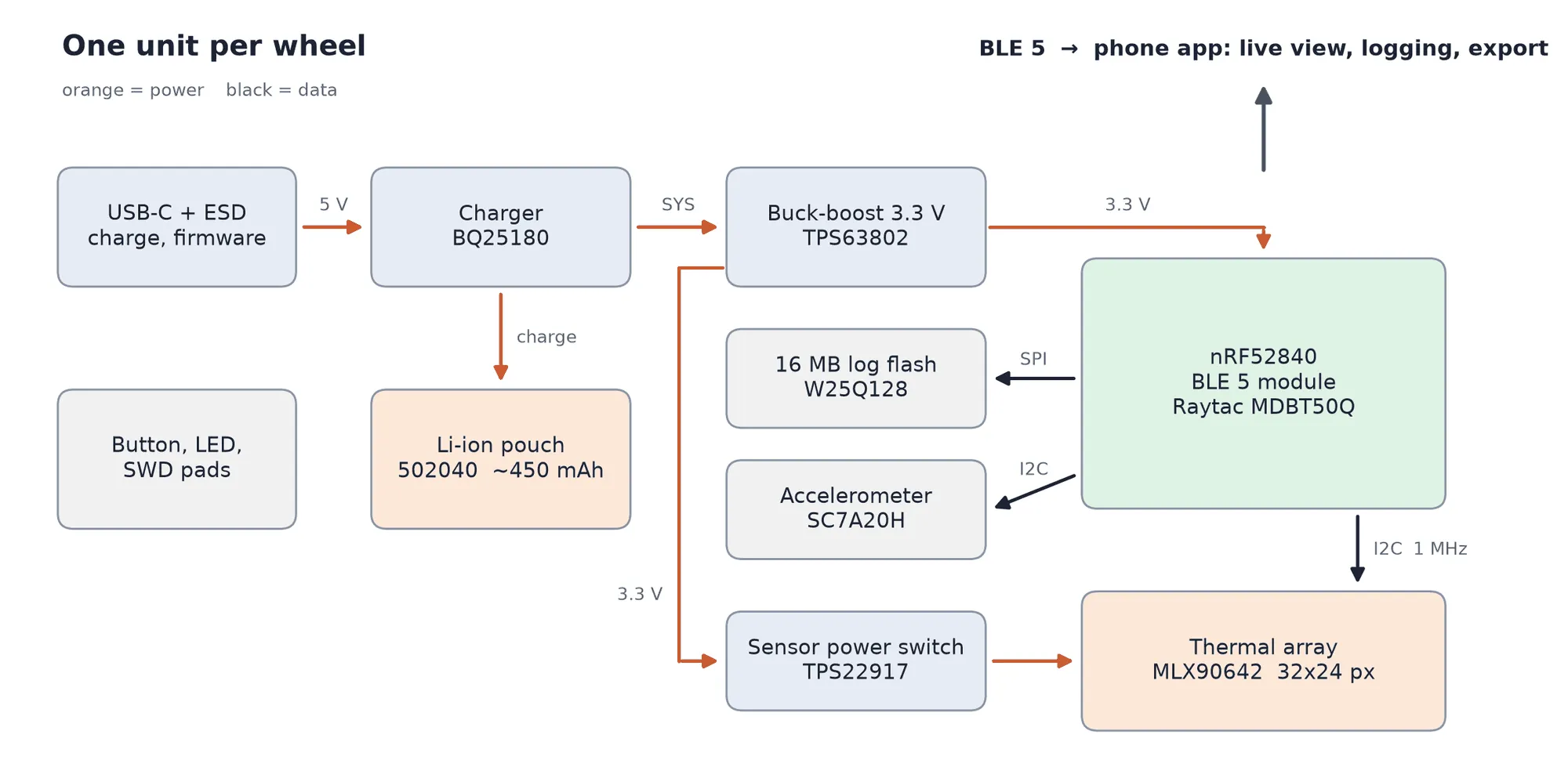
- 32 x 24 pixel thermal array, 8 frames a second
- Battery
- About 11 h estimated, against a 6 h target
- Stage
- Parts chosen and placed; tracks not yet routed
- Tools
- KiCad 10, nRF52840, Melexis MLX90642, nRF Connect SDK (Zephyr), Flutter, Python
Problem
How the heat spreads across a tyre’s tread tells a driver a lot about the car’s setup. A hot inner edge points to too much camber, and a hot centre to too much pressure. Racing teams measure this with infrared sensors in each wheel well, but the commercial kits cost several hundred dollars, which puts them out of reach of most club and track-day drivers.
The aim is a low-cost system for amateur and semi-pro drivers and teams:
- One unit per wheel well, standalone and self-powered.
- A temperature profile across the tread, good enough to compare the inner, middle and outer zones.
- A phone app over Bluetooth, showing all four tyres live and logging each session for review.
- At least 6 hours on one charge, enough for a full race day, charged in the unit by USB-C with no separate charger.
- Simple hardware, with the software doing the interpretation, so it is easy to install and use.
Where it started
The idea grew out of an earlier build for my own track cars. In September 2025 I ported RejsaRubberTrac, an open-source wireless tyre sensor, to a Seeed XIAO nRF52840 board. Its infrared sensor reads 16 temperatures across the tread. The port reordered the sensor start-up, slowed the shared I²C bus for reliability, packed the readings into Bluetooth packets for the RaceChrono lap timer app and added battery monitoring. It works on the bench, and it showed what a purpose-built unit would need: more pixels, a proper battery and charger, and a body designed to be aimed.
Choosing the parts
The thermal array sets most of the design.
- Melexis MLX90641: 16 x 12 pixels, rated to 125 °C and 12 mA. The microcontroller has to do the temperature calibration maths.
- Melexis MLX90642 (chosen): 32 x 24 pixels, so four times the detail, for a lower price. It calculates temperatures on the chip, which keeps the firmware simple. It draws 28 mA and the available grade is rated to 85 °C.
The 85 °C limit was accepted because the wheel well is not expected to get that hot, and the battery limits the unit first anyway: a lithium-ion cell should stay under about 60 °C. The two sensors share a footprint and pinout and have different I²C addresses. So the board and firmware accept either, and the MLX90641 can be fitted if testing shows more heat than expected.
The other parts were chosen around it:
- Radio: an nRF52840 Bluetooth 5 chip in a Raytac module that is already radio-certified, so the product doesn’t need its own radio approval. A cheaper module was rejected because no certification evidence could be found.
- Power: a TI BQ25180 charger from USB-C, and a TPS63802 buck-boost converter that holds 3.3 V across the whole battery range.
- Sensor power switch: lets the firmware power-cycle the sensor if it hangs.
- Accelerometer: wakes the unit when the car moves and puts it to sleep when parked, so there is no power switch to forget.
- 16 MB flash: logs each session on board, so nothing is lost when the phone is out of range.
- Battery level: read from a simple voltage divider instead of a fuel-gauge chip. The load is steady, so the voltage is a good enough guide, and it saves a part.
Form factor
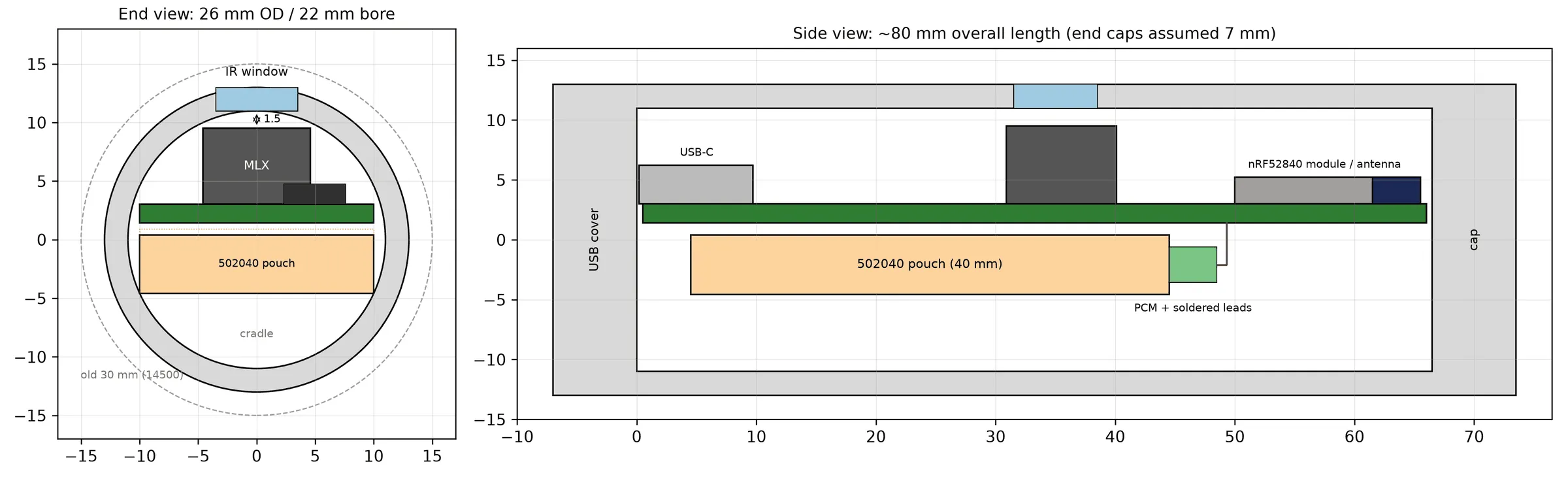
The unit is a cylinder with the sensor looking out through a flat window in its curved wall. It mounts with its axis parallel to the axle, so turning it in its bracket aims the sensor at a different point on the tyre. The sensor’s long pixel axis runs along the cylinder, across the tread. A serrated bracket locks the angle in 5° steps so vibration can’t move it, with markings on the body for repeatable setup. The body is light-coloured plastic: a metal tube would block Bluetooth.
The first layout used a removable 14500 cell, which needed a 30 mm diameter. Switching to a 502040 lithium-ion pouch cell (about 450 mAh) with soldered leads brought it down to 26 mm. The pouch sits in a cradle under the board, with room left for it to swell. A cross-section check showed that the board’s width, not the battery, sets the diameter: a 20 mm board needs about a 22 mm bore whatever sits under it.
The board
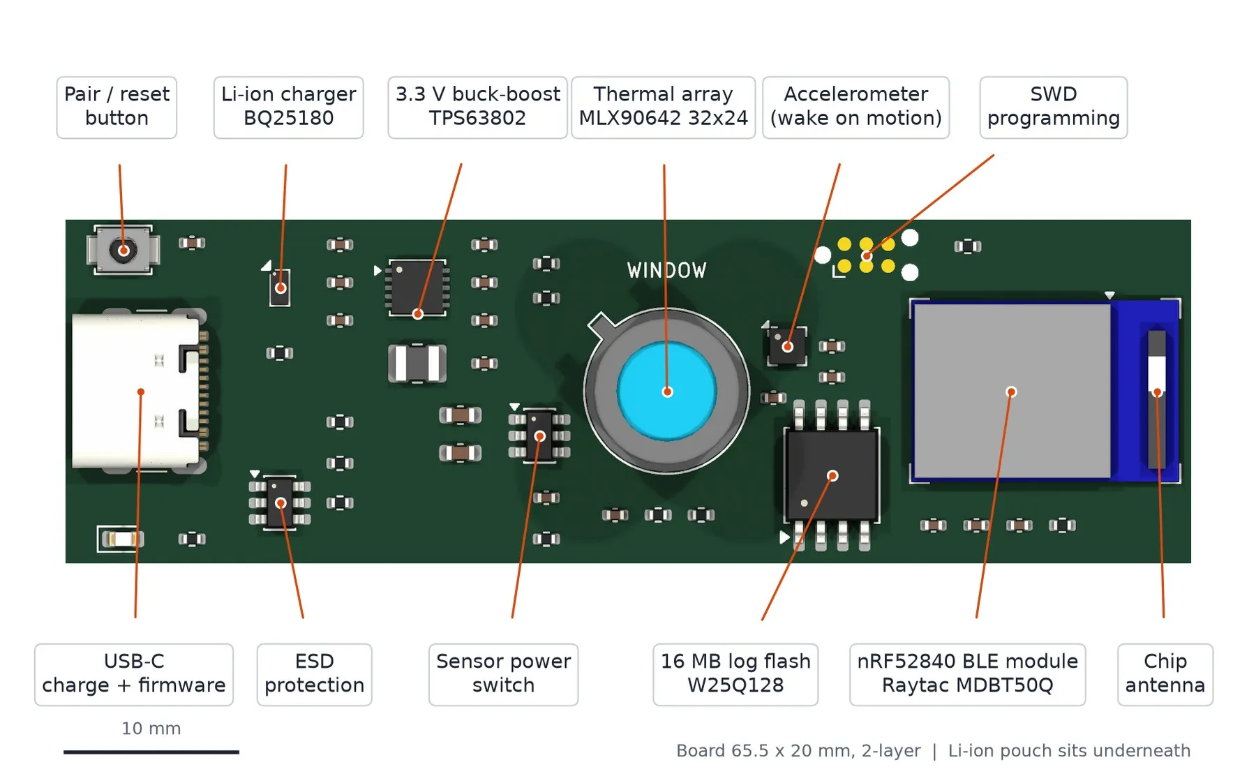
The first layout is a placement study: all the parts on a 65.5 x 20 mm, two-layer board, checked for clearances but not yet wired. The thermal sensor sits in the middle under the window. The USB-C port is at one end and the radio module’s antenna at the other, past the end of the battery.
3D model loads when you scroll here.
The placement study. Select a part to find it on the board.
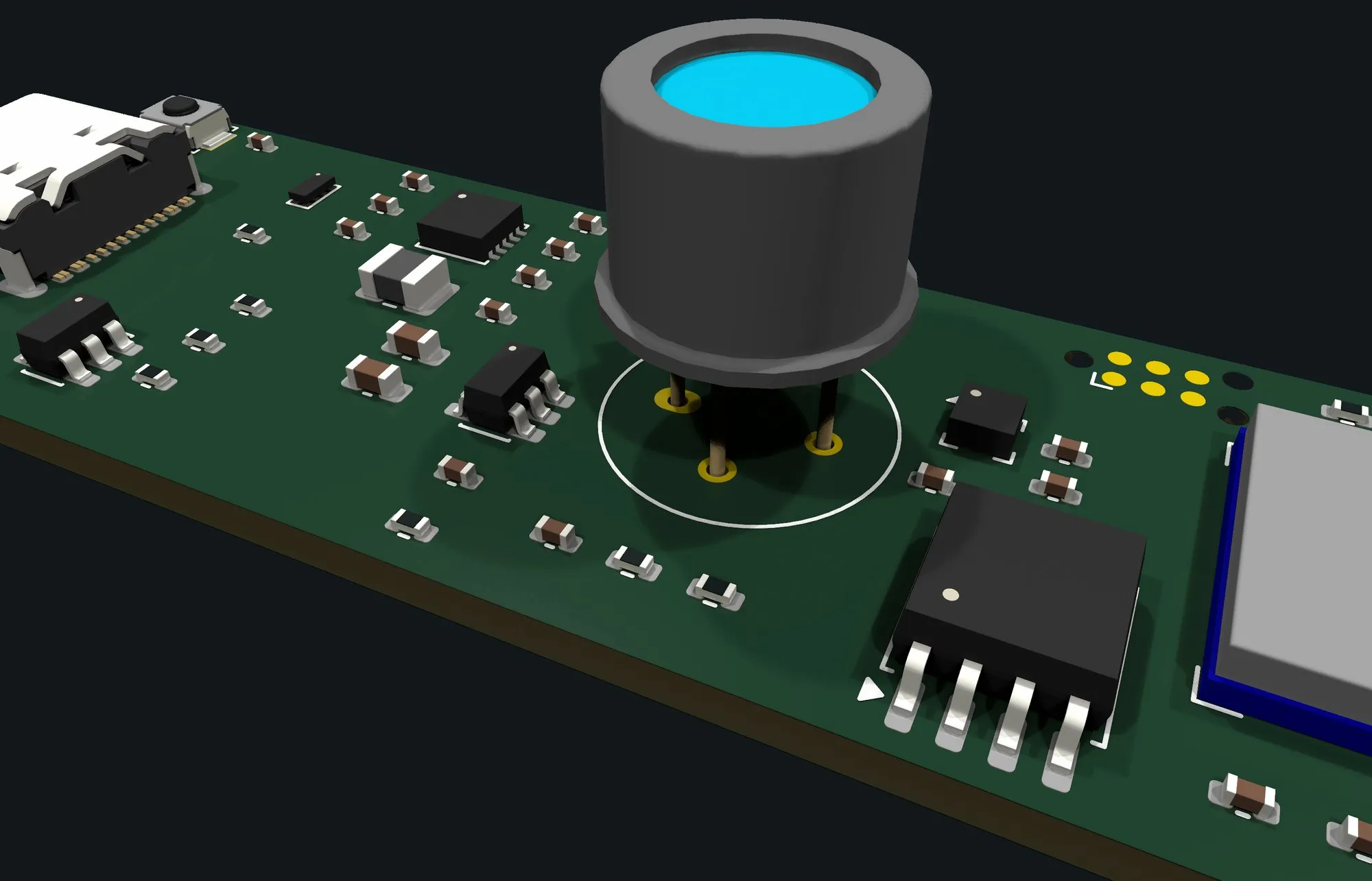
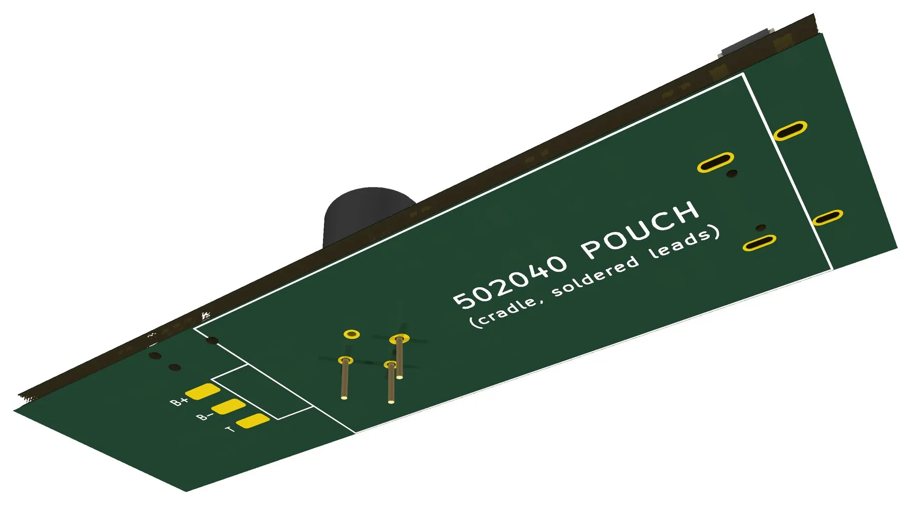
Battery life. The estimated draw is about 32 to 34 mA, most of it the thermal sensor. Allowing 20% for ageing and cold, the pouch cell gives about 11 hours, against the 6 hour target.
Logging. A temperature profile across the tread eight times a second, plus a full image every 10 seconds, comes to about 14 MB over 6 hours. That only just fits the 16 MB flash, so the next step is to compress the profiles or fit a 32 MB chip.
Next steps
Before the custom board is made, a proof of concept on off-the-shelf boards will answer the open questions in a real car:
- How many pixels land on the tread at the real mounting distance, with the wide (110°) and narrow (45°) lens options.
- How hot the wheel well gets during and after a session, to confirm the 85 °C sensor is safe.
- Whether Bluetooth is reliable from all four corners to a phone in the cabin.
- The real current draw, and so the battery size.
After that come the schematic and routed board, the firmware and the phone app, which will include an aim mode that shows the live image with the tyre edges marked to guide installation. The first market is Australia, then the United States.