Bucket wheel excavator prototype
Won a field of about 15 first-year teams, moving more than 6 kg of rice in five minutes against about 2 kg for the runner-up.
- For
- The University of Queensland
- Context
- First-year engineering design project, team of six
- My role
- Team leader and lead designer
- Year
- 2018
- Tools
- Fusion 360, CNC router, 3D printing, Plywood fabrication
Requirements
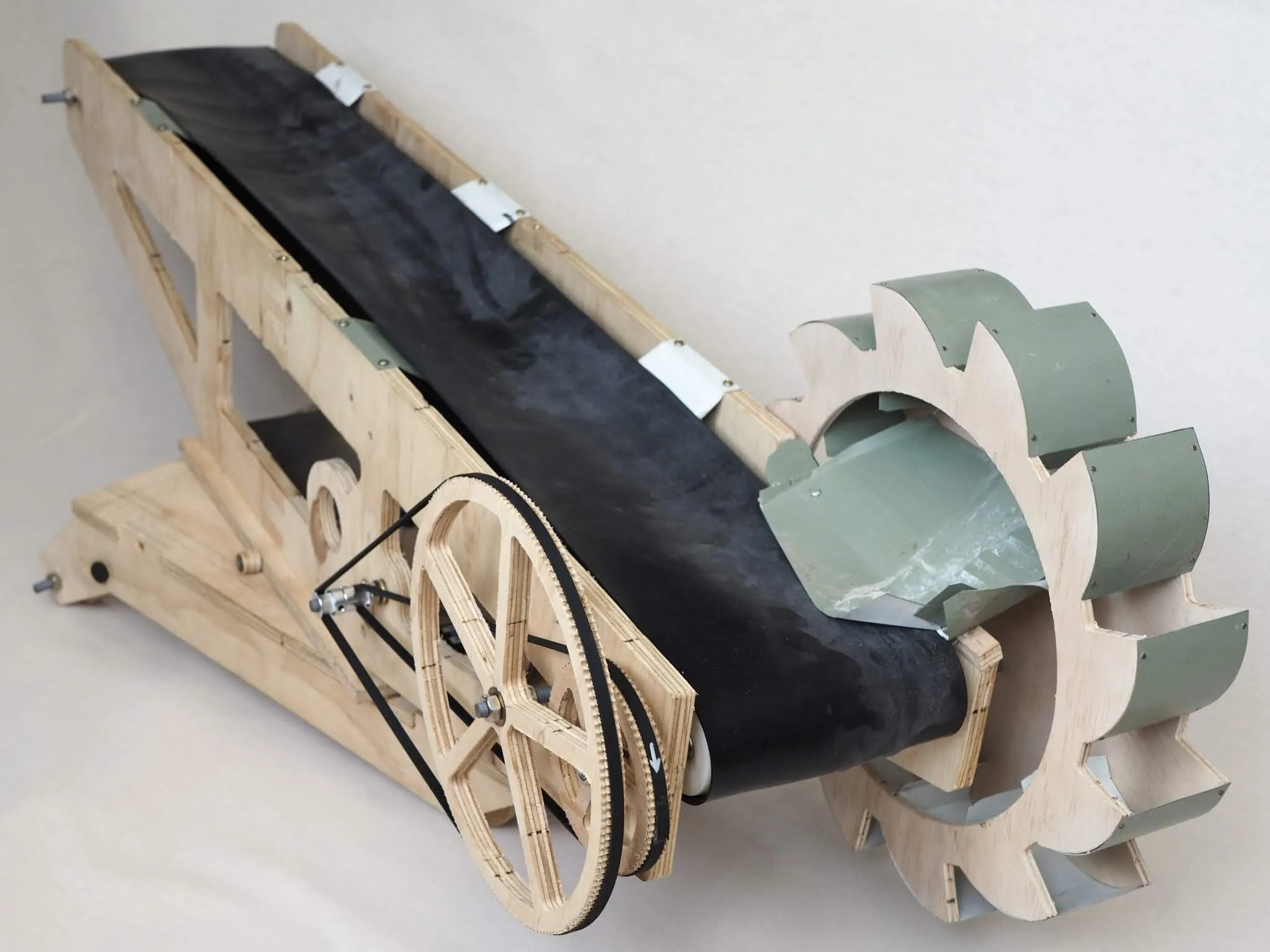
The Faculty of Engineering asked first-year teams to design, build and demonstrate a prototype bucket wheel excavator. It had to perform four set motions within limits on size, material, working space and budget. In the final demonstration it was judged on how much rice it moved from a muck pile to a discharge point in five minutes.
Design
I led the team and designed the machine apart from the bucket wheel geometry, along with the design for manufacture, the prototyping and all of the electronics. Options for the drive train, bucket wheel and superstructure were compared against power efficiency, structural strength, excavation rate, ease of operation and maintenance, and sustainability.
The decisions that won the competition:
- Power first. The wheel and conveyor both need a lot of power and torque, so the powertrain was identified early as the likely limit on digging rate. A large, powerful but low-cost electric motor was chosen and geared down for torque.
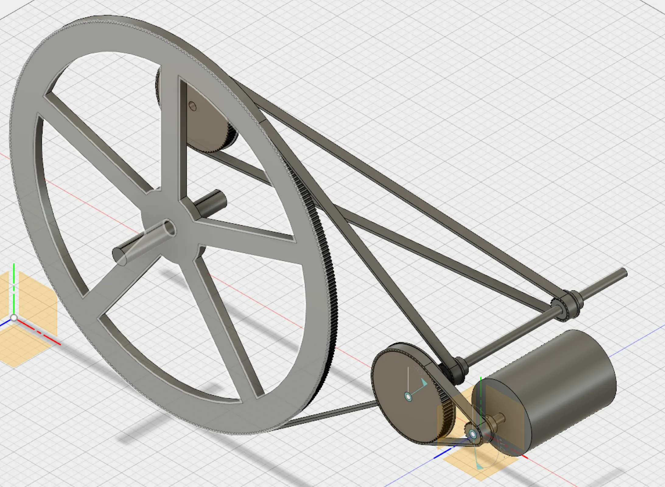
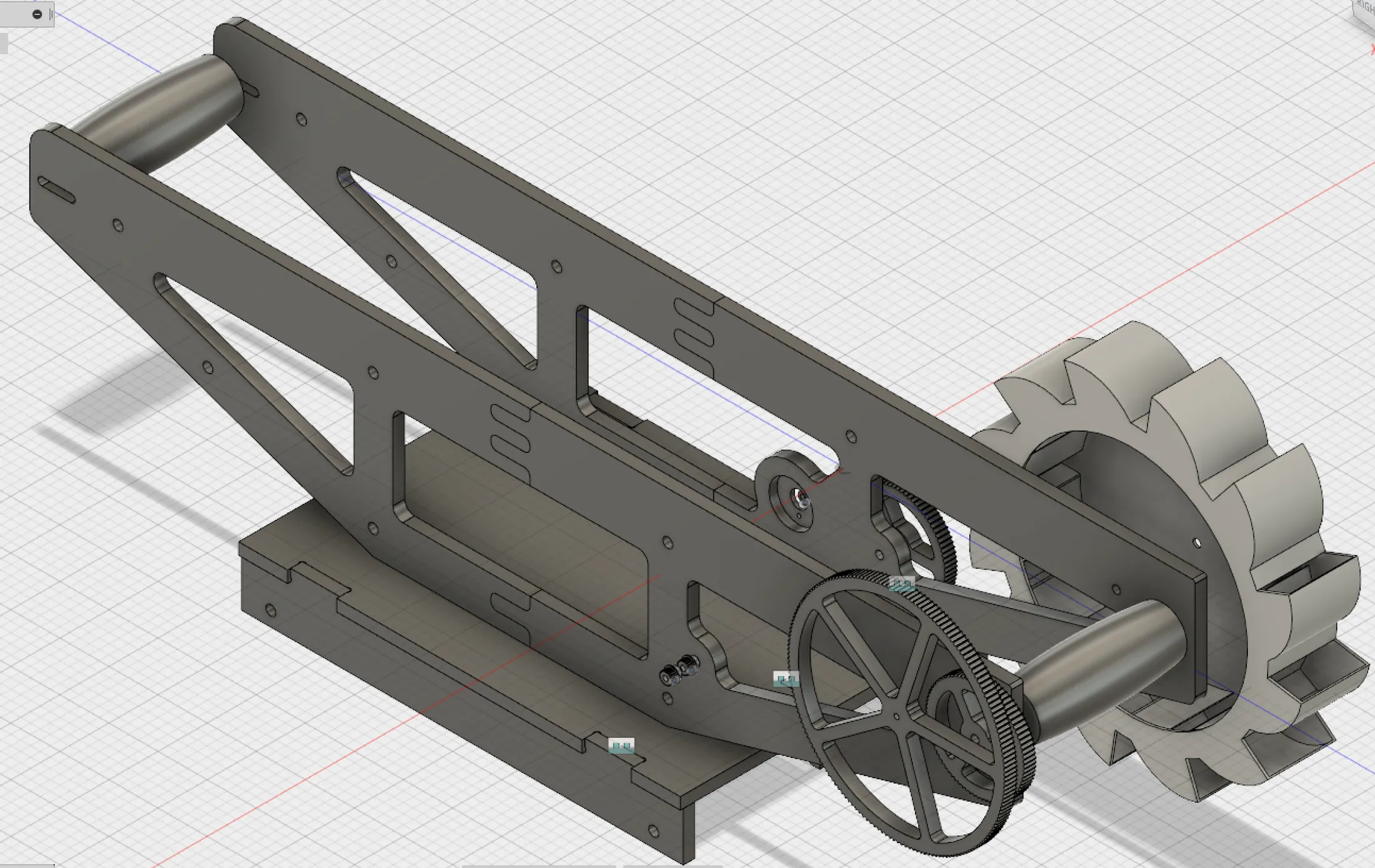
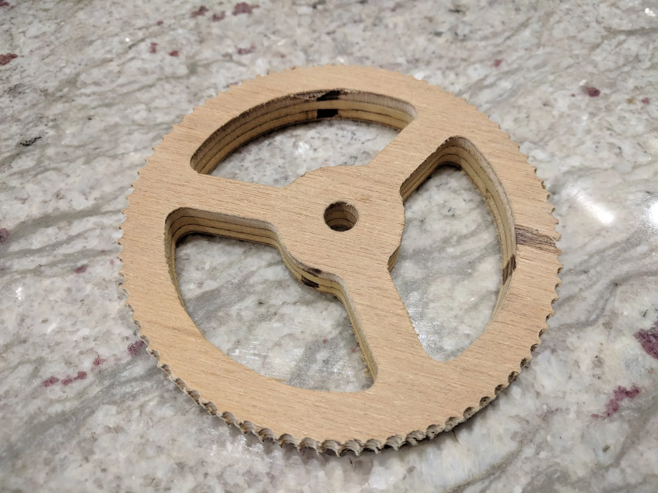
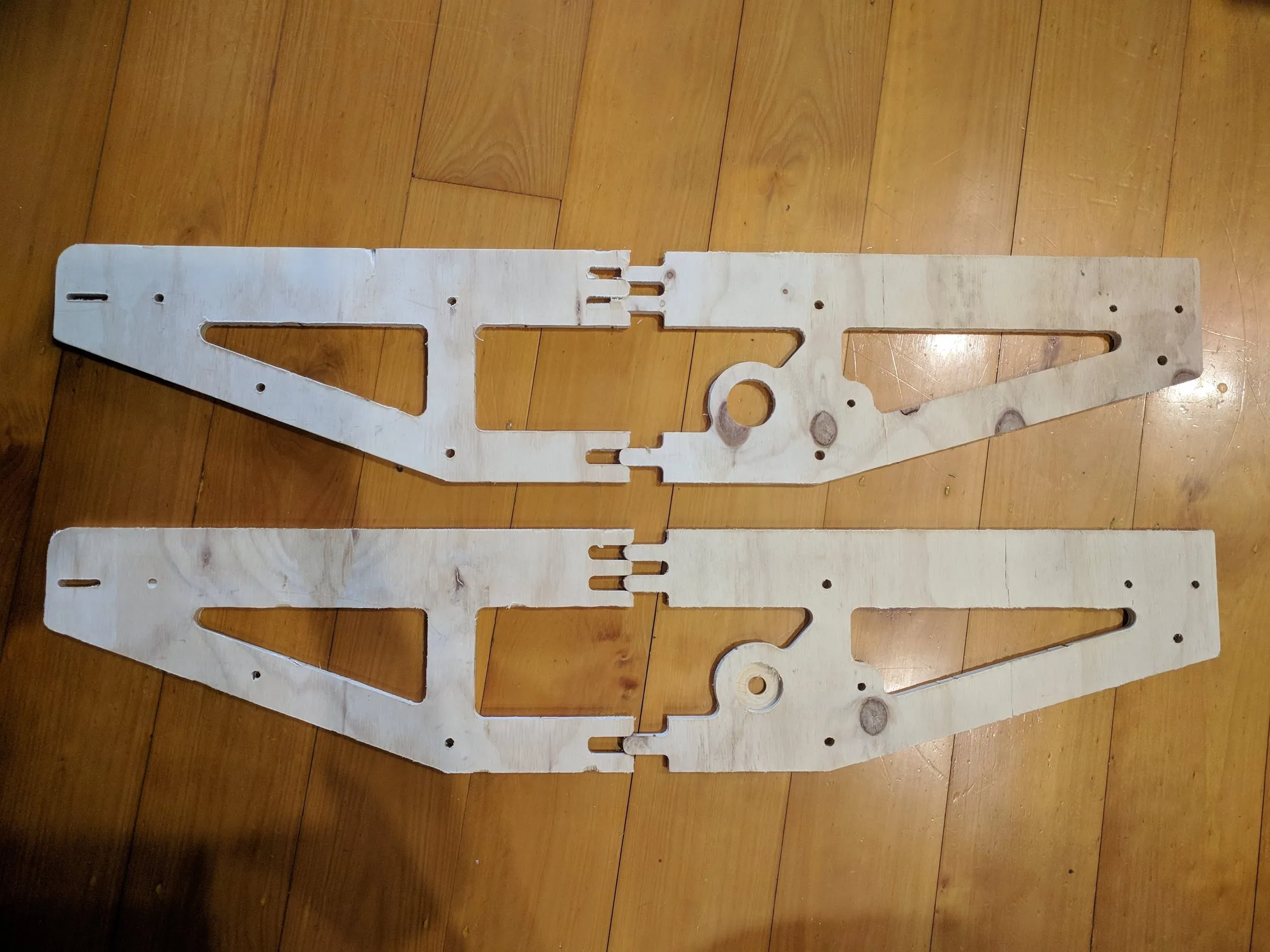
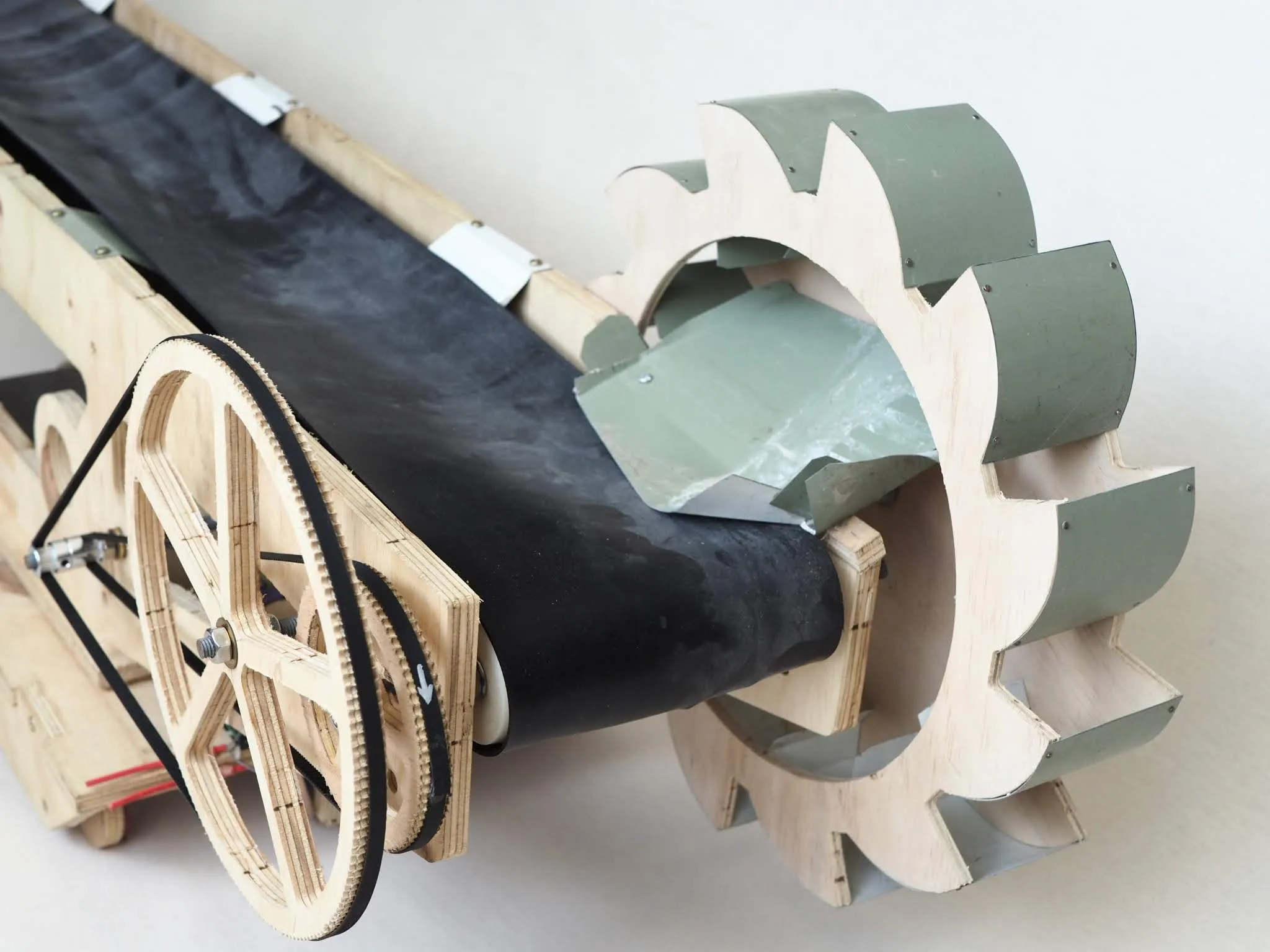
- A custom gearbox in the frame. Off-the-shelf gearboxes within budget were very limited. After assessing the options, the drive became a belt-and-pulley reduction with pulleys CNC-cut from plywood and built into the frame, so the frame itself carries the bearings. The pulleys were deliberately overbuilt so they could never be the failure point. The worst case was a motor stall, which did no damage and only meant taking smaller bites.
- One motor, two jobs. The rules allowed up to four motors, intended for the wheel, the conveyor, driving and sweeping the arm. One larger motor drove both the wheel and the conveyor through a jackshaft: the first reduction ran from motor to jackshaft, then a slower ratio went to the bucket wheel and a slightly faster one to the conveyor.
- A tilting wheel. The motor this freed up powered a mechanism that raises and lowers the bucket wheel. It could dig right down to the floor and reach higher up the pile, where other teams’ wheels stalled at a fixed depth and left rice they could not reach.
- Self-centring conveyor rollers. The rollers were crowned, like those on a belt sander, so the belt tracks to the centre. Teams using U-shaped rollers had belts ride up the edge or come off.
Build
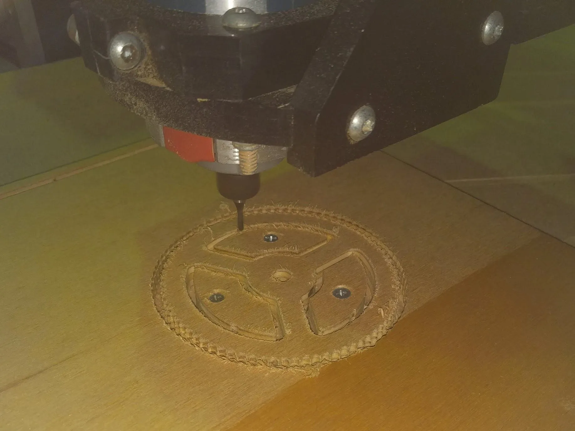
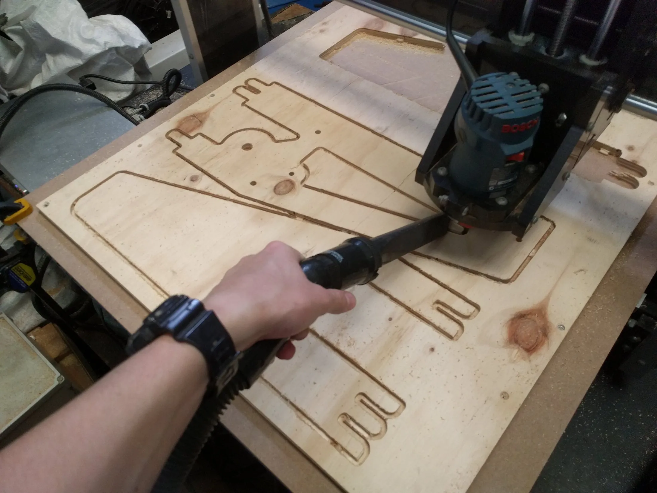
The frame plates and large gears were modelled in Fusion 360, programmed with its CAM tools and cut from plywood on a CNC router. Smaller gears were 3D printed.
Outcome
The excavator won the competition out of about 15 teams. It moved a little over 6 kg of rice in the five minutes, against about 2 kg for the second-placed team.
Next steps
Thrust bearings held many of the shafts in place. They did not affect the result, but every bolt had to be checked for tightness before each run. Conventional ball bearings would remove that maintenance step.