Wheel roundness measuring device
Finds hidden wheel flats in about seven minutes, with one person and the wheelset still on the train.
- For
- Queensland Rail
- Context
- Honours thesis with The University of Queensland
- My role
- Sole designer and builder, from concept to field test
- Year
- 2021–2022
- Measuring time
- About 7 minutes per wheel, one person
- Field testing
- Mayne rail yard, October 2022
- Tools
- Fusion 360, Arduino and C++, Mitutoyo digital indicator, Waterjet cutting, Manual lathe, FDM printing
Problem
When a train’s brakes lock, the wheel skids and grinds a flat spot into its tread. Every revolution after that slams the flat into the rail, damaging track, bogies and the wheel itself.
Queensland Rail finds flat spots in two steps. A wheel impact load detector in the track flags suspect wheels, then fitters inspect them by eye in the workshop. The difficulty is that a flat’s sharp edges wear round within days. By the time the wheel reaches the workshop it can look perfectly round while still being out of round, so defective wheels go back into service.
Rolling stock engineering expected the detector to flag a large share of the suburban fleet once its limits were switched on. They needed a quick, reliable way to confirm what the detector was seeing.
Requirements
- Measure a wheel while the train stands in the workshop, without removing the wheelset.
- Be faster and easier than jacking the wheels and measuring by hand.
- Cost less than commercial systems, using instruments Queensland Rail already owns.
- Be built from parts and services available in Brisbane.
- Introduce no new safety risk, with engineering controls for any that appeared.

Design
The tool does three jobs: lift the wheel, turn it, and measure it.
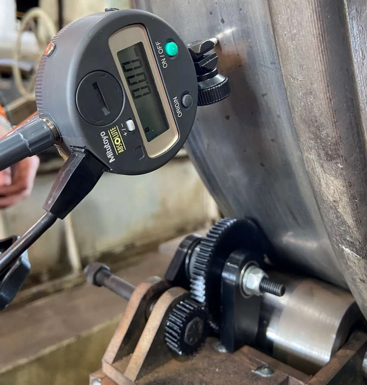
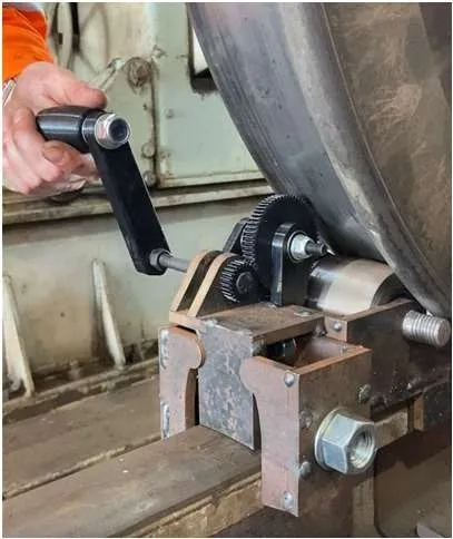
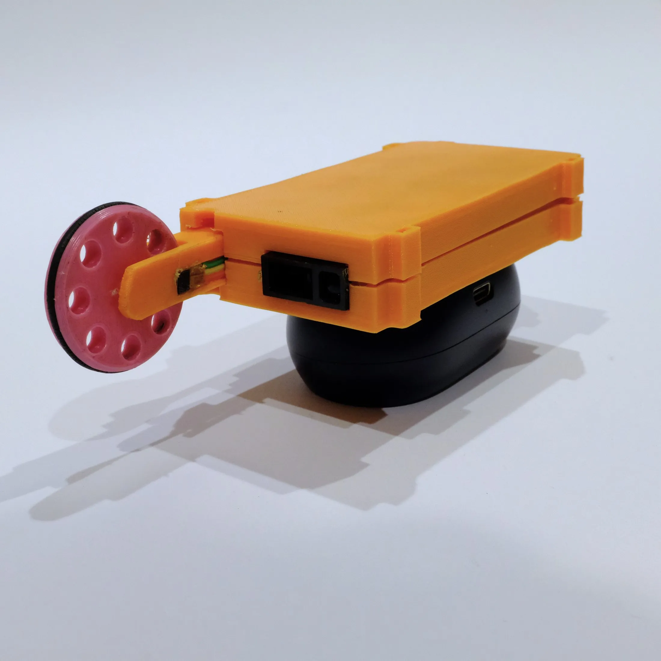
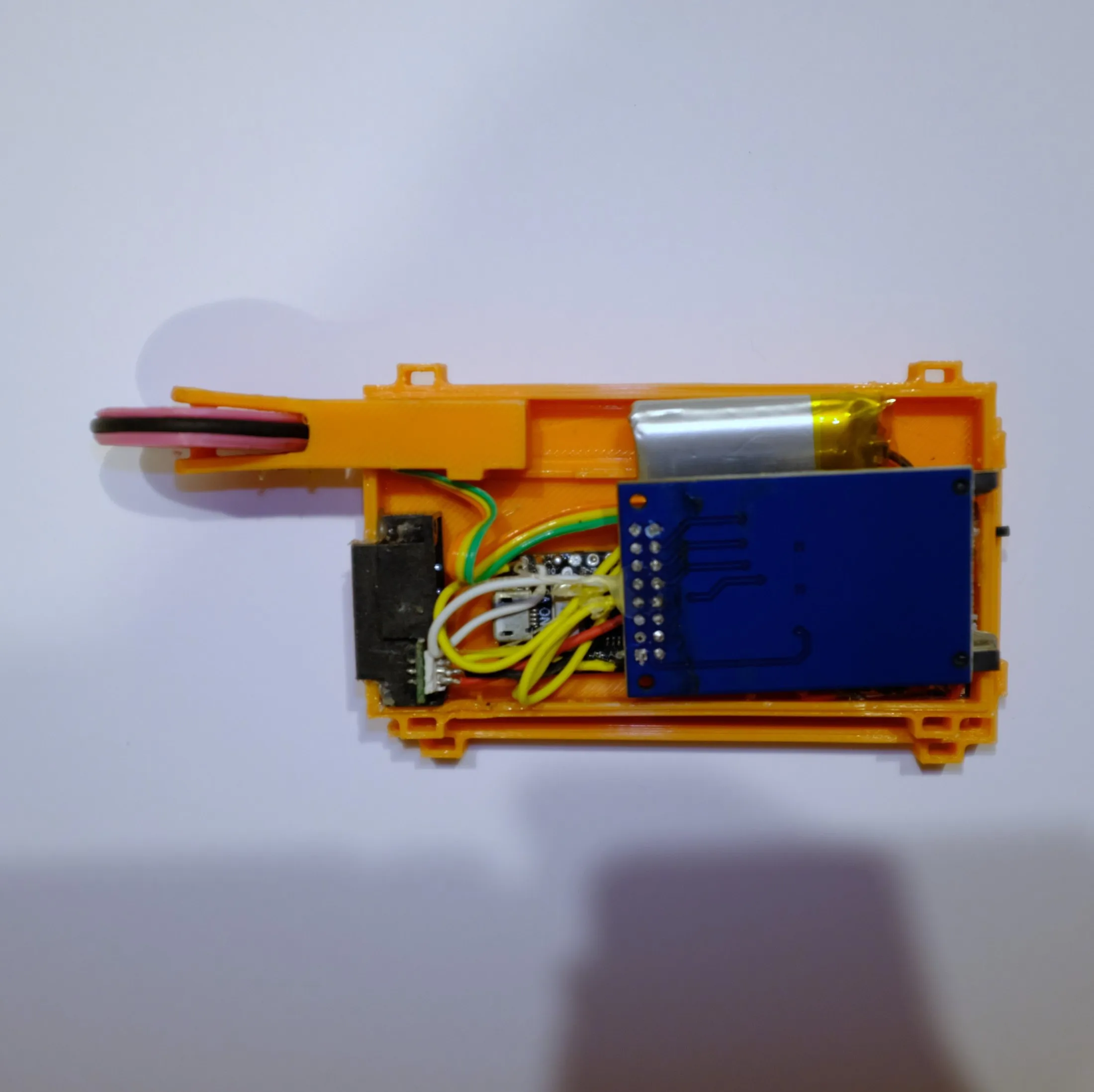
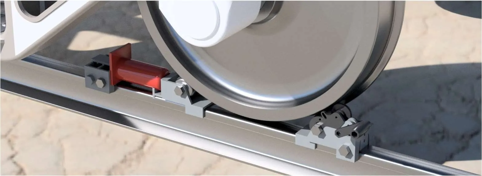
Two steel rollers clamp to the rail on either side of the wheel. A bottle jack pushes them together, which lifts the wheel off the rail so it rides on the rollers. A hand crank drives one roller through a gear reduction and a GT2 belt, turning the wheel slowly. An encoder in the pulley tracks the roller’s angle while a Mitutoyo digital indicator, set 70 mm from the wheel face as Queensland Rail’s wheel defect standard requires, reads the tread. A small logger writes each angle and displacement pair to an SD card.
Explore the assembly below. It is the original CAD, trimmed to a short length of rail.
3D model loads when you scroll here.
Select a part to see what it does, or explode the assembly to see how it fits around the wheel.
Build
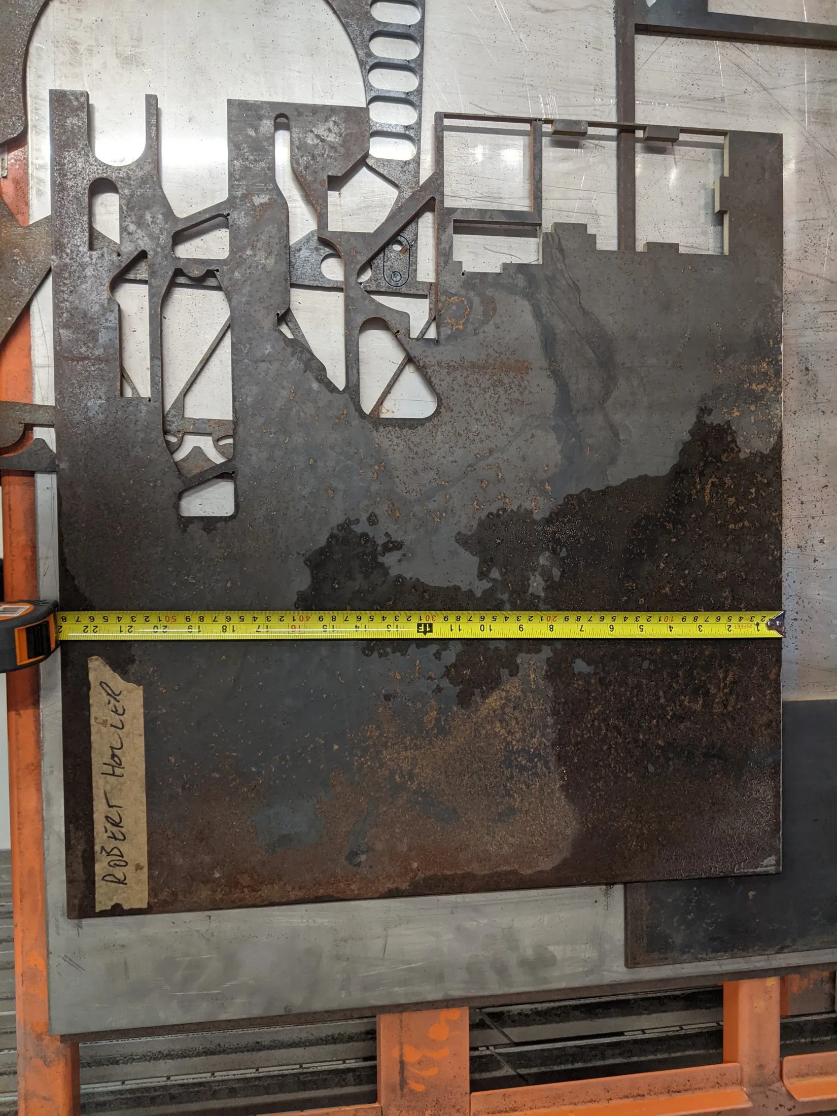
The frame is 8 mm steel plate cut on a waterjet, with box joints so the parts self-align for welding. The rollers are 80 mm AS 1045 bar, turned on a manual lathe. The drive assembly is 3D printed. Everything else is off the shelf, so a workshop can source replacement parts locally. Plate thickness was sized with a parametric FEA study: the geometry was fixed by function first, then thickness was adjusted until the strength target was met.
Testing and iteration
The prototype was tested twice at Mayne rail yard in October 2022.
On the first day the electronics failed, so only the mechanical systems were assessed. Installing, clamping and jacking took two and a half minutes per wheel, faster than the existing jacking method. Rotation was the weak point: the worn wheel rode on the outer edge of each roller, putting its full load on one bearing until it bound. The first gearbox also lacked the strength and ratio to turn the wheel.
The rollers had been modelled on a new wheel profile, but wheels in service are worn. Before the second test I added a chamfer that moves the contact patch to the centre of each roller, so both bearings share the load, and rebuilt the gearbox with a higher ratio.
On the second day the device lifted, turned and measured the wheel, logging the roundness runs below. The new gearbox worked but was not yet reliable enough, which makes it the first priority for the next revision.
- Readings
- 55
- Highest
- –
- Lowest
- –
Raw readings in millimetres, straight from the logger’s SD card. The logger stored displacement only, so readings are spaced evenly around the wheel. Runs that caught a dial glitch from spinning too fast are left out.
Outcome
- One person can set up and measure a wheel in about seven minutes. The previous approach took a team of staff days.
- The train stays where it is, and the wheelset never comes off.
- It uses measuring instruments Queensland Rail already owns, for much less than commercial systems.
- The output is a plain text file that plots straight into a roundness profile.
Next steps
- Replace the hand crank with a motor, or a socket for a cordless drill. That makes rotation constant, which also cuts dial errors caused by spinning too fast.
- Put the logger on one custom board with the microcontroller, SD card and battery charging. It would be cheaper and tougher.
- Lock the bottle jack to the frame for an extra layer of safety.
- Turn the rollers on a CNC lathe. Each one took about ten hours by hand.