Drill cabin window guard
Redesigned so drill operators can see their work, while keeping falling-object protection to AS ISO 3449.
- For
- Glencore
- Context
- Rolleston open cut coal mine
- My role
- Undergraduate design and maintenance engineer
- Year
- 2021
- Standard
- AS ISO 3449, identical to ISO 3449:2005
- Machines
- Rotary blast-hole drills DR05 and DR06
- Tools
- Fusion 360 CAD and simulation, Impact FEA, Engineering drawings
Problem
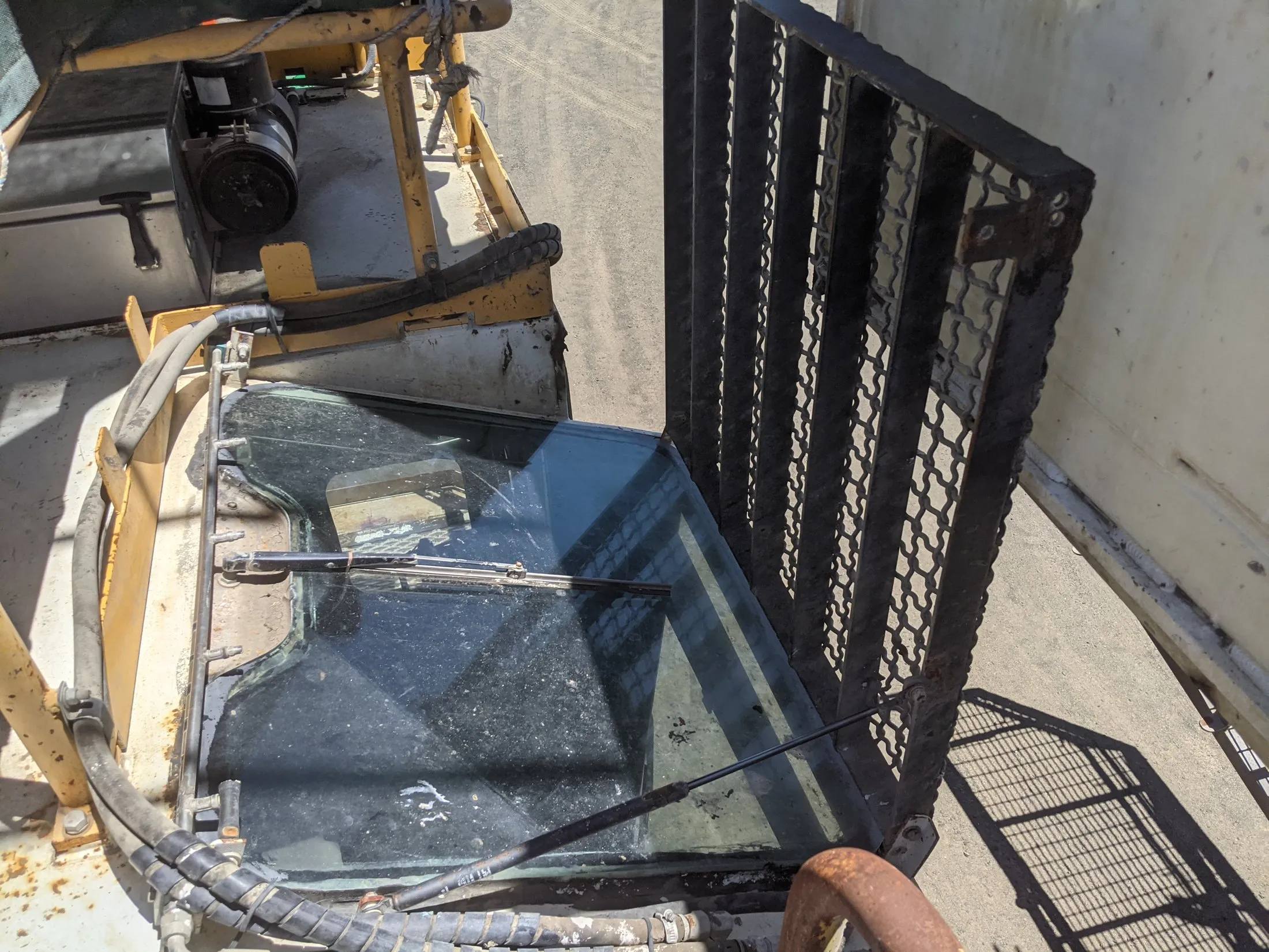
The window guard on one of the site’s blast-hole drills had broken off, and the maintenance department needed a replacement designed in-house. The guard is a falling object protective structure, or FOPS, so it had to meet the standard.
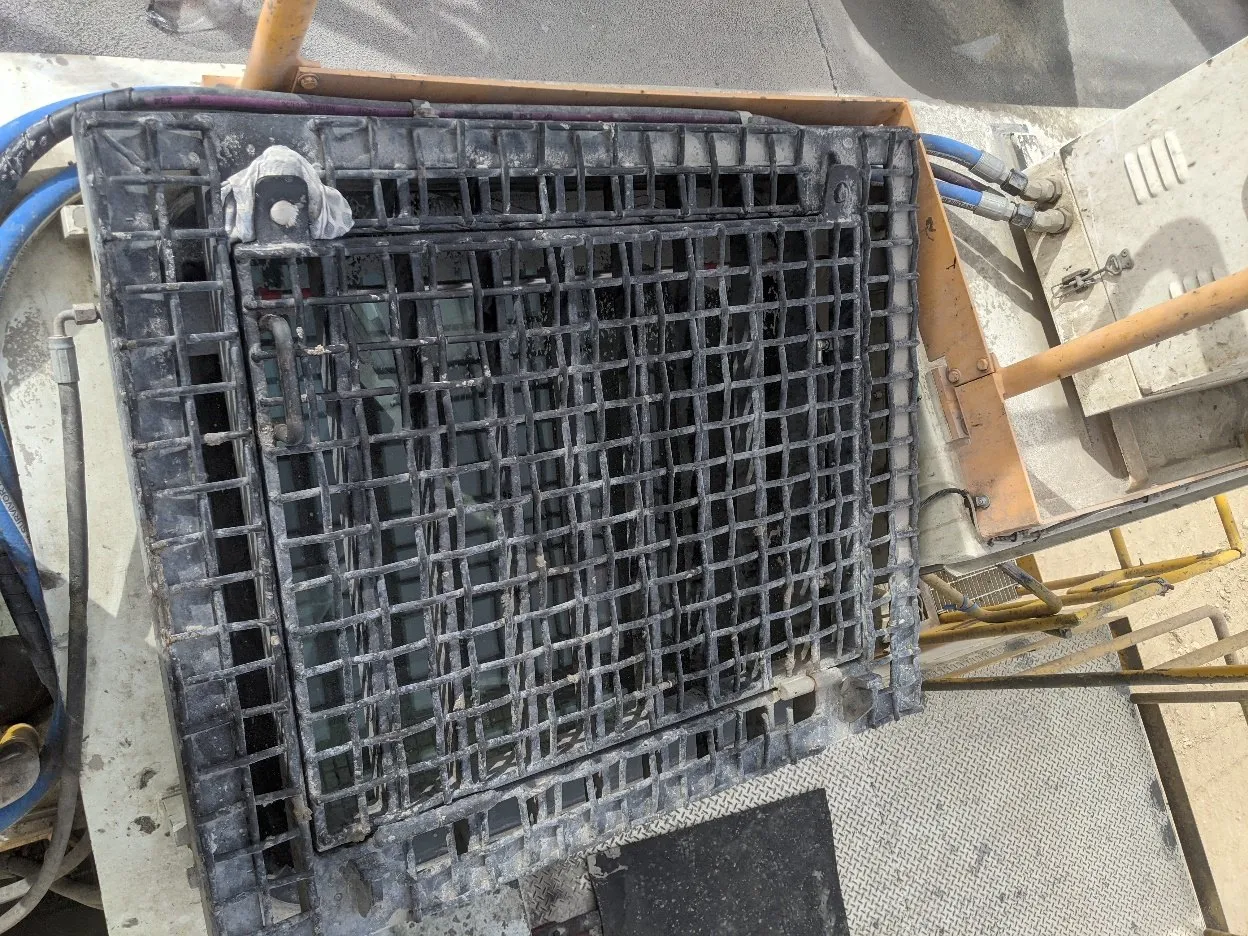
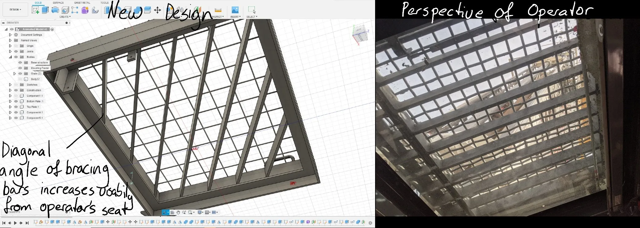
Operators look up through this window throughout the shift to check the top of the drill boom. With the bars of the existing design set square to the window rather than to the operator’s seat, they had to lean forward and to the side to see past them. That adds fatigue and costs situational awareness, in an environment where falling rock is a constant hazard.
Requirements
- Meet the falling-object requirements of AS ISO 3449.
- Fit that drill’s window exactly.
- Be buildable by the site boilermakers.
- Give the operator a clear view of the boom tip, a target added beyond the original brief.
- Reduce pinch points around the moving parts.
- Survive continuous mine-site use.
- Be simple for operators to open, clean behind and secure again.
Design
The design started in the cab. The guard on a similar machine showed how its protection worked, and talking with the operator and sitting in the seat showed exactly where the view was blocked.
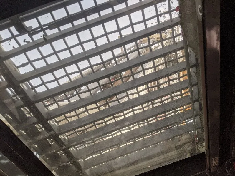
The key decision followed from that. The flat bars run along the sightline from the operator’s seat to the boom tip, at about 28 degrees rather than square to the window, so the operator looks along their thin edge instead of at their face. The bars still cover the area that has to stop a falling object, but block far less of the view.
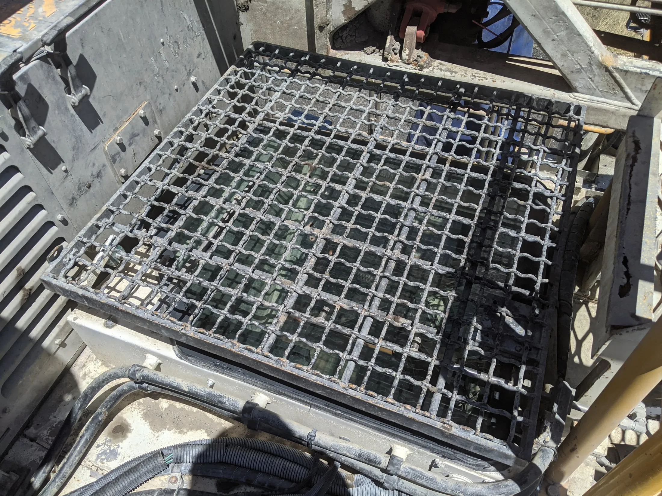
The guard is a hinged frame of 60 × 60 × 4 mm square hollow section, with 60 × 12 mm flat bars forming the grate.
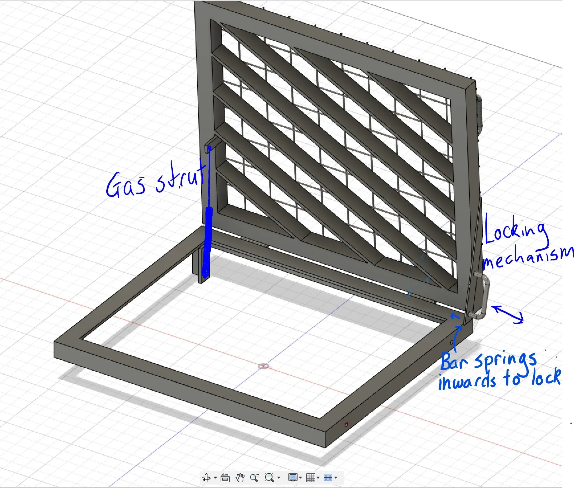
The window also has to be cleaned. The frame hangs from a separate 60 × 60 × 10 mm angle surround on weld-on bullet hinges, so the whole guard folds open. A gas strut takes the weight as it opens, so lifting it does not strain whoever is cleaning, and a lock holds it shut.
Analysis
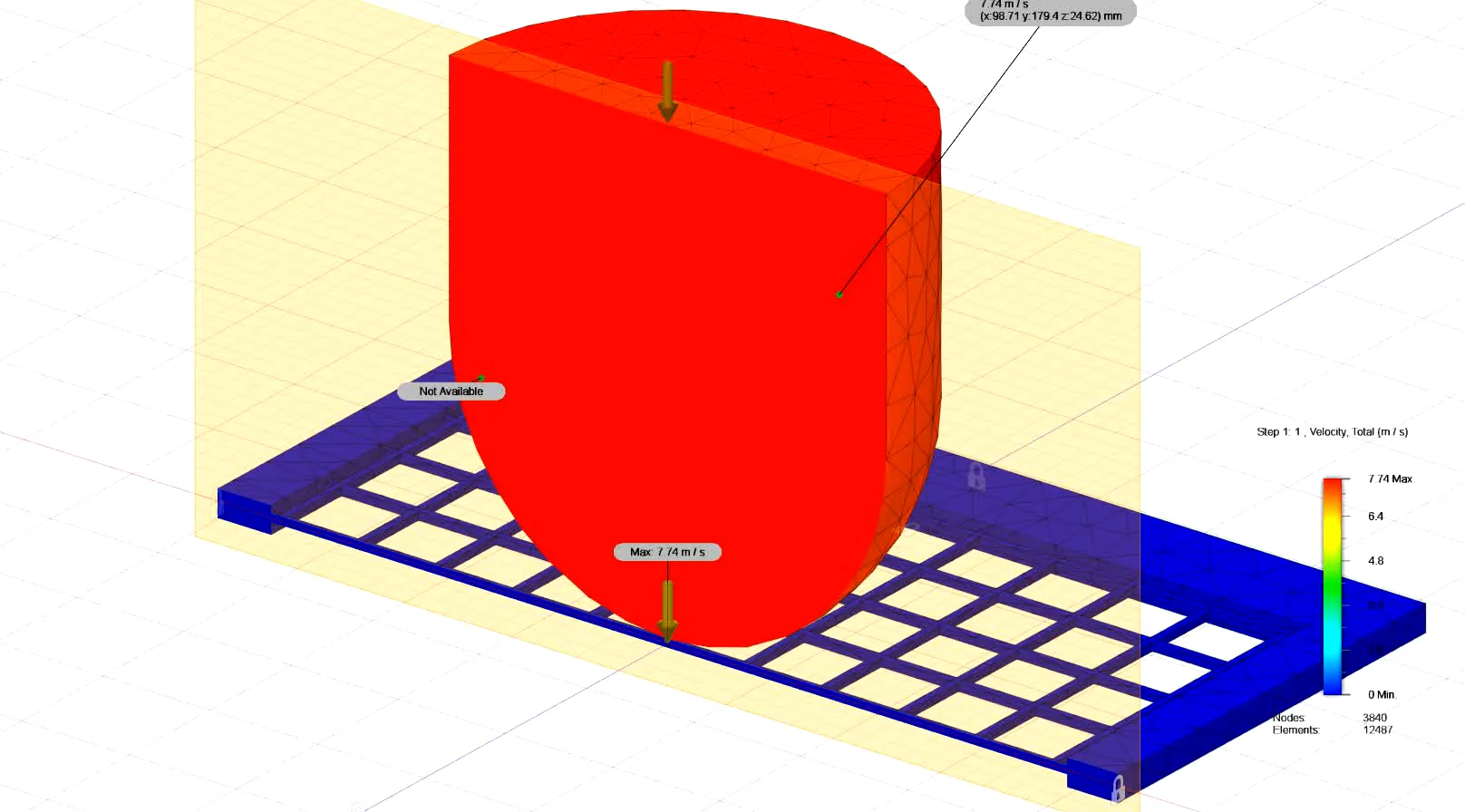
The full assembly was modelled in CAD and checked with finite element analysis against the standard’s impact case. A far more severe case was then run to establish how much margin the structure had. Both showed the guard absorbing the impact without failure of the bars or frame.
Outcome
The deliverable was a validated CAD model and full drawing package, handed to an RPEQ engineering contractor for final design review, fabrication, certification and installation on the drills. The design met every point in the brief, bringing the guard up to the current standard while giving operators a clearer view of their work.
The placement also showed how decisions made in the engineering office play out on the workshop floor, and the value of consulting early with fitters and engineers who had decades of experience on these machines.